
The V5 Inertial Sensor combines a gyroscope and accelerometer provided by an ICM-20602 chip to measure a robot’s orientation, angular velocity, and acceleration on three axes. The Inertial Sensor is more formally called the IMU (Inertial Measurement Unit).
Inertial Sensors are one of the most widely used VEX sensors in competition, because they allow a robot to accurately determine its absolute heading on the field. This is an important step in robot localization (position tracking) and motion control for accurate turns. Inertial sensors can also be used to detect collisions, tips, and measure actions that involve tilting the robot (such as driving up a ramp or climbing).
Creating an Inertial Sensor
Using the Peripherals struct passed to our main function, we can create an Inertial Sensor from any one of the 21 SmartPort fields on it.
#[vexide::main]async fn main(peripherals: Peripherals) { let mut sensor = InertialSensor::new(peripherals.port_1);Create an Inertial Sensor on port 1.}Calibration
Before we can use the Inertial Sensor, we have to calibrate it first. Calibration ensures that the orientation readings are accurate by having the sensor measure its baseline acceleration and angular velocity while completely still.
To perform calibration, call the calibrate() method and await it:
#[vexide::main]async fn main(peripherals: Peripherals) { let mut sensor = InertialSensor::new(peripherals.port_1); _ = sensor.calibrate().await;}Calibration usually takes around 1-3 seconds, but can take longer if the sensor fails to calibrate on the first attempt and retries. During this process, the robot should remain completely still.
Any movement or vibration during calibration will cause the sensor to think it’s spinning while at rest. It is strongly recommended to avoid moving the robot after calibration before the autonomous period begins.
Frame of Reference
The Inertial sensor takes measurements on three axes — called X, Y, and Z.

The sensor uses the north, east, down (NED) coordinate system, where the Z-axis points downwards in the direction of the earth’s gravity. While this system is common in the aerospace industry, it’s less typical in ground vehicles, since it has some implications for how we use the sensor’s orientation readings (we’ll discuss this further down).
Mounting Orientation
During calibration, the Inertial Sensor determines which direction is “up” by detecting which axis experiences gravity through its accelerometer. This allows the sensor to align its axes consistently regardless of how it’s mounted. In other words, the Z-axis will always point downward, even if the sensor is installed upside-down or sideways.
The Inertial Sensor should always be mounted flat and level. Mounting it at an incline relative to gravity will lead to inaccurate readings. Don’t do that.
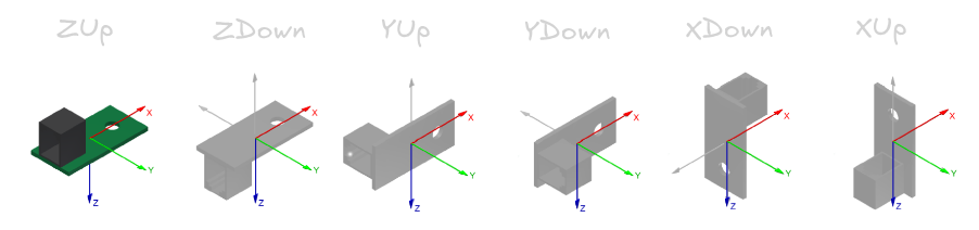
After calibration, you can check the orientation the sensor detected using the physical_orientation() method:
#[vexide::main]async fn main(peripherals: Peripherals) { let mut sensor = InertialSensor::new(peripherals.port_1); sensor.calibrate().await.unwrap(); println!("Sensor was calibrated while facing: {:?}", status.physical_orientation());}This method returns one of six possible orientations, based on how the sensor is mounted relative to the axis labels printed on its casing. For example, an orientation of XDown indicates that the direction labeled “X” on the top of the sensor is facing downward toward gravity.
The axis labels on the sensor shouldn’t be confused with axes we measure from after calibration, though. The Z-axis will still always point downwards, regardless of if the physical orientation is XDown.
Measurements
As mentioned earlier, the Inertial Sensor combines a gyroscope and an accelerometer.
- The accelerometer measures acceleration on the three axes.
- The gyroscope measures angular velocity on the three axes.
- The sensor integrates these readings over time to measure the robot’s absolute orientation (yaw, pitch, and roll).
Acceleration
To measure the robot’s raw acceleration with the IMU’s accelerometer, we can use the acceleration method.
#[vexide::main]async fn main(peripherals: Peripherals) { let mut sensor = InertialSensor::new(peripherals.port_1); sensor.calibrate().await.unwrap(); if let Ok(acceleration) = sensor.acceleration() { println!( "x: {}G, y: {}G, z: {}G", acceleration.x, acceleration.y, acceleration.z, ); }}The acceleration.x, acceleration.y, and acceleration.z values give us the robot’s measured acceleration on each axis in units of G-force.
Angular Velocity (“Gyro Rate”)
We can use the sensor’s gyroscope to measure the robot’s angular velocity (how fast it is rotating) on each axis using the gyro_rate function.
#[vexide::main]async fn main(peripherals: Peripherals) { let mut sensor = InertialSensor::new(peripherals.port_1); sensor.calibrate().await.unwrap(); if let Ok(rates) = sensor.gyro_rate() { println!( "x: {}°/s, y: {}°/s, z: {}°/s", rates.x, rates.y, rates.z, ); }}This gives us values for each axis in degrees per second. For example, positive rotational velocity about the Z-axis implies that the robot is rotating clockwise.
Heading & Rotation
Here’s what you’re probably here for. If we want to determine the robot’s absolute heading or orientation, we can use the sensor’s integrated gyroscope, which continuously tracks how far the robot has turned since the sensor was last calibrated or reset. This is accessed using the rotation() and heading() functions.
rotation()gives the total accumulated rotation of the robot in degrees, which can exceed 360° or go negative.heading()gives the current compass-like heading, which is always wrapped between 0° and 360°.
#[vexide::main]async fn main(peripherals: Peripherals) { let mut sensor = InertialSensor::new(peripherals.port_1); sensor.calibrate().await.unwrap(); if let Ok(rotation) = sensor.rotation() && let Ok(heading) = sensor.heading() { println!("Rotation: {:.2}°, Heading: {:.2}°", rotation, heading); }}
Because the sensor uses a Z-down frame of reference, the robot’s heading will increase as the robot turns clockwise. This goes against the typical unit circle system of angles, where counterclockwise rotation results in a positive angle change. When using the IMU in a system that uses cartesian coordinates or trig functions like sin/cos, you must convert the raw IMU heading into a standard angle system by inverting it. This can be done as follows:
(360.0 - raw_imu_heading).rem_euclid(360.0)vexide also keeps internal offsets to allow for setting and resetting the sensor’s heading and rotation without fully recalibrating. This means you can “zero out” the robot’s orientation at any time to get a new source of truth for where you’re facing.
For instance, if we want the robot’s initial orientation to be 90 degrees instead of 0, we can use the set_heading and set_rotation methods to offset the initial heading/rotation values.
#[vexide::main]async fn main(peripherals: Peripherals) { let mut sensor = InertialSensor::new(peripherals.port_1); sensor.calibrate().await.unwrap(); _ = sensor.set_heading(90.0); _ = sensor.set_rotation(90.0);}Similarly, if we wanted to reset the heading or rotation to zero, we can use reset_heading and reset_rotation.
#[vexide::main]async fn main(peripherals: Peripherals) { let mut sensor = InertialSensor::new(peripherals.port_1); sensor.calibrate().await.unwrap(); _ = sensor.reset_heading(); // equivalent to `_ = sensor.set_heading(0.0)` _ = sensor.reset_rotation(); // equivalent to `_ = sensor.set_rotation(0.0)`}
Heading and rotation are tracked separately in vexide. Using set_heading/reset_heading will not have any effect on the angle returned by the rotation method.
Euler Angles
When using heading and rotation, we measure the rotation of the robot on one axis — the yaw, or the rotation about the Z-axis. We can also do the same for the other axes using the euler method. This gives us a set of Euler Angles as three angles in degrees:
ais the yaw of the robot. This is effectively the same asheading.bis the pitch of the robot, or how tilted forward/backward it is.cis the roll of the robot, or how tilted left/right it is.
use vexide::prelude::*;use std::time::Duration;#[vexide::main]async fn main(peripherals: Peripherals) { let mut sensor = InertialSensor::new(peripherals.port_1); sensor.calibrate().await.unwrap(); if let Ok(angles) = sensor.euler() { println!( "yaw: {}°, pitch: {}°, roll: {}°", angles.a, // yaw angles.b, // pitch angles.c, // roll ); }}While the robot’s roll and pitch are less often used, they can be useful for detecting tipping and traversing field elements that require the robot to tilt itself. For example, we can use the b component (pitch) reported by the sensor to detect the robot’s angle when climbing up a ramp.

Troubleshooting
Although the Inertial Sensor is one of the most common and useful sensors in competition, it is also extremely finnicky and prone to failure. This section covers the most common failure modes of the sensor and how to mitigate them.
Loss of Power, “Micro-disconnects”
When the Inertial Sensor loses power — even momentarily — its readings become useless until it is re-calibrated. Poor wiring may cause the sensor to briefly lose connection with the Brain without the Brain registering that a disconnect occurred. This is especially problematic because the sensor will automatically try to recalibrate itself when power is restored. Since the robot is often in motion when this happens, the calibration will fail and the sensor will report bad data for the remainder of the match.
This is fundamentally a hardware problem. The first thing that you should do is ensure a secure connection between the Brain and the sensor by wiggling the wire at both ends. If either side is intermittent, start by replacing the wire. If the issue persists, you may need to use a different port on the Brain or use a new sensor.
This issue can be detected in software by periodically checking if the sensor has started calibration again without you explicitly telling it to:
use vexide::prelude::*;use std::time::Duration;#[vexide::main]async fn main(peripherals: Peripherals) { let mut sensor = InertialSensor::new(peripherals.port_1); sensor.calibrate().await.unwrap(); loop { let sensor_failure_occurred = sensor.is_calibrating().unwrap_or(true); if sensor_failure_occurred { panic!("Disconnect occurred"); } sleep(Duration::from_millis(InertialSensor::UPDATE_INTERVAL)).await; }}In the event that the sensor disconnects, you may wish to switch to a backup source for your readings. For example, if you were using the sensor to measure heading, you could switch to a secondary sensor or swap to measuring wheel travel for a less accurate approximation.
If you have access to a second IMU, having one available as a backup to switch to is a good idea in the event that this happens.
Calibration Failure
During calibration, there are several things that can go wrong. By far the most common cause of calibration failure is movement or vibrations during the calibration period. If the robot is not at rest when sensor.calibrate().await is running, the sensor will believe that it is rotating while the robot is sitting still.
When a bad calibration occurs, vexide has no way of reporting it to you directly since VEXos has no error reporting mechanisms for this, however a common indicator of a failed calibration is the calibration timing out or taking longer than usual. By timing how long the calibration attempt takes, we can establish an “expected time” for a successful calibration and have the user manually restart the program if the calibration took longer than expected. Here is a sample function that times how long a calibration attempt took and prints it to the controller screen:
use vexide::prelude::*;use std::time::Instant;pub async fn calibrate_imu( controller: &mut Controller, display: &mut Display, imu: &mut InertialSensor,) { println!("Calibrating IMU"); _ = controller .screen .try_set_text("Calibrating...", 1, 1); let imu_calibration_start = Instant::now(); if imu.calibrate().await.is_err() { eprintln!("Calibration fail!"); _ = controller .screen .try_set_text("Calibration fail! ", 1, 1); return; } let imu_calibration_elapsed = imu_calibration_start.elapsed(); println!("Calibration completed in {:?}.", imu_calibration_elapsed); _ = controller .screen .try_set_text(format!("{:?} ", imu_calibration_elapsed), 1, 1);}To effectively use this, you should familiarize yourself with how much time a successful calibration takes. This can vary from sensor to sensor, but in testing usually took ~1.72 seconds. If the sensor took significantly longer than the expected time to calibrate, simply restart the program to re-calibrate until the sensor calibrates successfully.
Mounting Considerations
A poorly mounted Inertial Sensor will not perform well. As previously mentioned, the sensor must not be mounted at an incline or tilt from the ground. It may be mounted upside-down or sideways on any of its faces, but must stay level with the ground during calibration.

If the Inertial Sensor is mounted near a mechanism on the robot that causes vibrations or sudden mechanical shock (such as a flywheel, catapult, or puncher), the sensor will lose accuracy faster. Care should be taken to mount the sensor at a structurally secure location away from such mechanisms. You may wish to mount the sensor on a shock-absorbent material, such as mesh or rubber (ensuring that the sensor is still level with the ground).

Additionally, excessive pressure on the sensor’s outer housing has been found to cause issues with calibration and connection reliability. Avoid over-tightening the sensor’s mounting screw or pressure-mounting the sensor inside of a C-channel flange.
Static Charge & Electromagnetic Interference
The presence of electrical noise as a result of nearby EMI, line noise, or statically charged objects may temporarily impact the readings of an Inertial Sensor’s gyroscope. The MEMS gyroscope inside of the sensor uses the Coriolis effect to detect rotational motion. In the presence of significant interference, these delicate measurements may be masked by noise causing the sensor to report incorrect or skewed readings. Electrostatic discharge (ESD) also poses a risk of permanent damage to both the IMU and the Brain.
Many factors can lead to a buildup of static electricity when driving a robot, with the main causes being cold temperature and low humidity. Shielding the IMU entirely from interference and ESD is not an option in most cases, but there are ways to mitigate it:
- Avoid mounting the IMU extremely close to the ground, especially when driving on foam field tiles or carpeted floor.
- Avoid mounting the IMU near devices that emit significant line noise or maintain a magnetic field.
- Avoid using older wheels sold by VEX. Newer revisions use a more static-resistant material.
- Ensure the robot is being driven on newer VEX anti-static field tiles.
- Use anti-static spray or a similar compound.
Poor Factory Calibration
A small number of Inertial Sensors ship with a defect that causes error in their pitch and roll readings, making the robot think it’s slightly tipping or tilted when it’s level with the ground. This is a result of poor factory calibration in the sensor’s accelerometer, and can be fixed by following the instructions here.
This process should be done with care, and only when absolutely necessary! Please read the VEX article carefully before doing this, as it may damage the sensor or make the problem worse if done improperly.